
Servo I/O Board
++++ This page is also available in german ++++
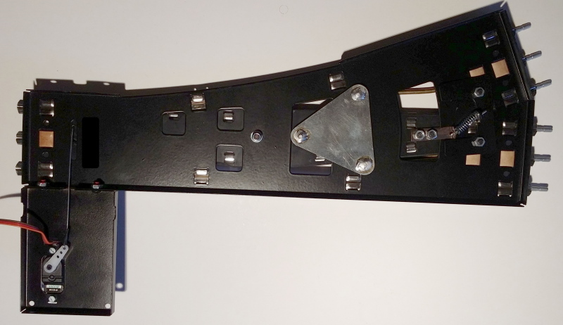
I was asked to develop a board for controlling model railroad tracks.
The tracks were actuated with servos.
The board can also be used by people without Arduino programming knowledge.
No problem with an Atmega328 and some software. The software was developed using the Arduino IDE
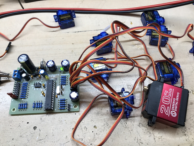
A separate circuit board has been made for real operation, since I generally don't like the Arduinos in real operation. The Arduinos are
excellent for development, but less suitable in real operation in my opinion.
Today servos are very cheap in many sizes and are a good alternative to solenoids when mechanics need to be moved.
Circuit
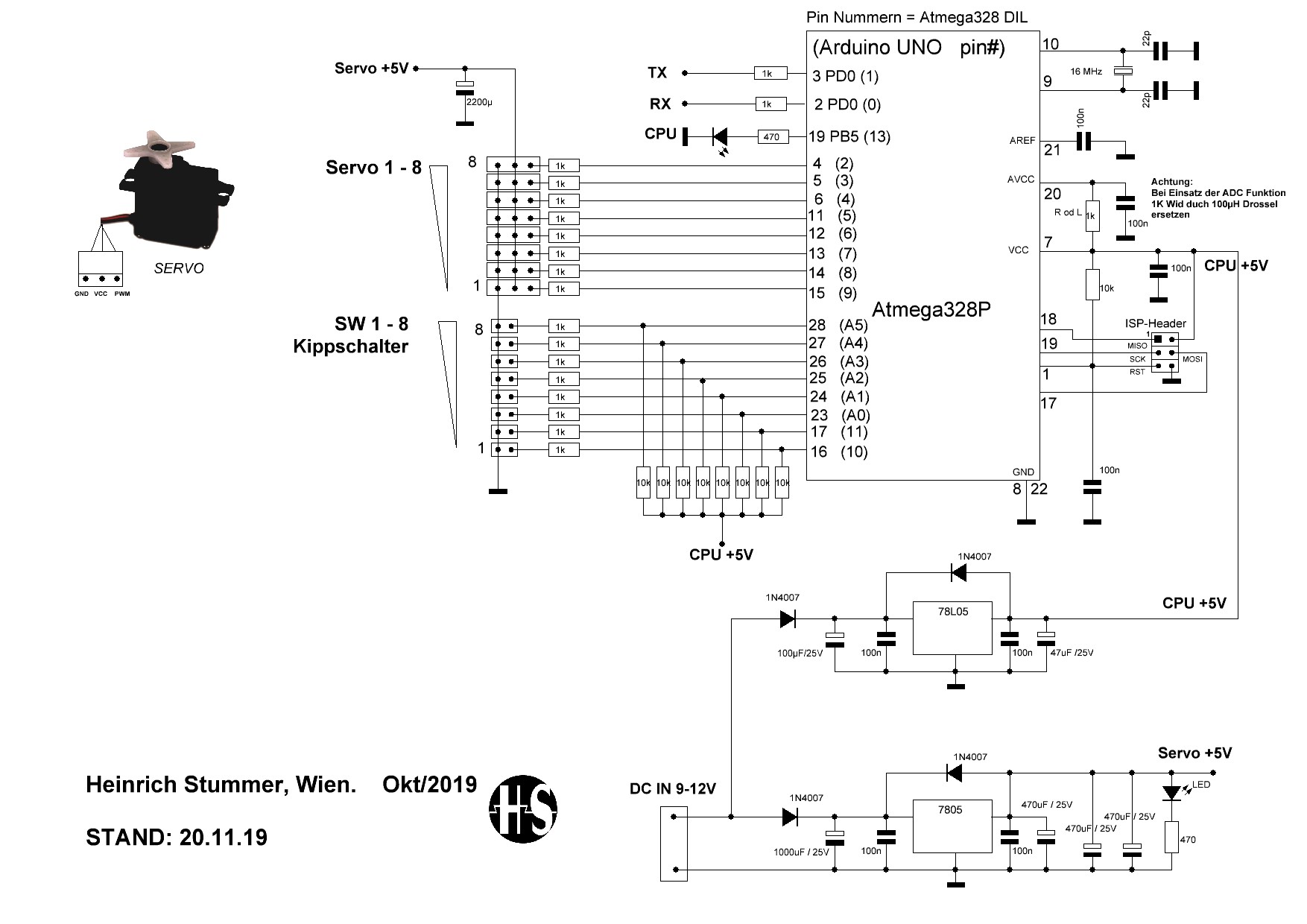
An Atmega328 with standard wiring is used as CPU. 16Mhz quartz, ISP connector for programming, I / O pins with protective resistors.
The board can of course also be used differently. Inputs A0-A5 can also be used as analog inputs.
When using the ADC function, the 1K resistor on pin 20 should be replaced by a 100µH choke (not used here).
Only populate the pull-ups when needed. Internal pull-up resistors can also be defined using software. But these are only active while
the sowftware ist running and does not protect the inputs when they board is not powered up. Therefore, the 10K resistors are provided as pull-up.
The pins can be configured for other applications as required.
The power supply is divided into two branches. A 78L05 supplies the CPU only.
There is also an extra branch with an extra 7805 for the servos. Current peaks, caused from the servos, have no effect on the CPU.
A 1N4007 is provided as reverse polarity protection. If a Traco TSR2 2405 controller with 2A output current is used instead of the 7805, the
1N4007 should be replaced by a 1N5408.
Servos are controlled with a PCM signal, the pulse width corresponds to the desired position in which the servo should move. The servo tried, as long
as the PWM signal is present, to hold this position, which then leads to high power consumption.
In this configuration, only two stable end positions are required, therefore the length of the switching command is set to 700 ms.
If the PWM signal is not present, mechanical forces on the servo arm can move the servo. It is not necessary to hold the positions here.
Board View and assembly
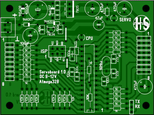
You can also supply the servos with an external 5V power supply if higher currents are needed. Do not populate the 7805 controller and the 5V here
from the power supply via the contact (controller 7805 OUT) to the board. The components in front of the controller are then omitted.
However, the CPU should always have its own 78L05 for save operation.
External voltage supply for large servos (optional)
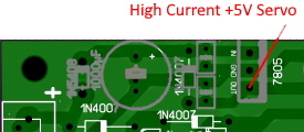
Special case only if high current servos are used.
Board template as pdf
Servoboard PDF PlatinenvorlageAssembly
- Populate the circuit board
- Flash Atmega328, either via ISP socket or externally.
- Mount servo 0 degrees position left lever. Normally with the switch open, the servo moves to the 0 degree position.
- Test Servo MAX degrees. The default value is 180 degrees (the servos never generally reach the values)
- optionally set the servo MIN and MAX value and the direction using the learning mode so that the value harmonizes with the mechanics.
Software description
The CPU LED flashes during normal operation. All switches are read and the servos are set afterwards.
Furthermore, the watchdog function of the CPU is activated with 4 seconds. The CPU stops at a supply voltage of less than 2.7V. (Fuse BODLevel)
To adjust the direction and deflection, each servo is individually adjustable. These values are permanently saved in the CPU's EEprom.
If the MISO pin is on GND with Power ON, the system branches to the optional learning mode. The bridge is only relevant when switched on and can then be removed immediately.
The MISO pin is not connected to a switch, so the learning mode cannot be switched on unintentionally.
The learning mode is shown in which the CPU LED does not flash. The learning mode is also not intended for continuous operation - no watchdog.
In normal operation, all servos are set at 0-180 degrees. In practice, the 180 degrees are not reached by the servomechanics. Depending on the servotype.
The learning mode is provided so that the deflection can be individually adapted to the application.
The deflection can be set in so-called learning mode for each servo 1-8 in 5 degree steps
You can also define whether MIN - MAX (servo) is assigned to OPEN - CLOSE (switch) or vice versa.
These values are stored in the EEprom of the Atmega328.
The learning mode is started by a wire from GND to MISO (pin1) of the ISP connector during Power ON.
In the learning mode there is no watchdog monitoring and the LED does not flash here.
The learning mode is intended for the adjustment of the deflection and the direction to the mechanics. The values are saved permanently in the EEProm.
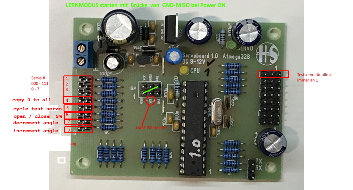
Ein Servo zum Test der Mechanik und zur Einstellung wird an den Servoausgang 1 angeschlossen.
The 8 buttons now have a different meaning.
Button 1 Servoaddress bit 0 - value 1
Button 2 Servoaddress bit 1 - value 2
Button 3 Servoaddress bit 2 - value 4
With this 0 - 7 the servos 1 - 8 can be addressed. The servo is ALWAYS in learning mode at servo port 1 !!
Address 0 = all switches open. Address 7 = all 3 switches closed. The 3 values are added and then form the servo address.
(The program counts internally from 0-7. The servos are numbered from 1-8 on the board.)
Button 4 Copies the setting from servo # 0 to # 1 - # 7, so that not all servos have to be taught individually.
Button 5 The servo moves MIN-MAX as long as this switch is closed. is to assess the movement on the mechanics.
Button 6 defines OPEN / CLOSE. Teach Servo MIN or MAX for OPEN and CLOSE.
Button 7 decrease the value in 5 degree steps. 0 is MIN.
Button 8 increase the value in 5 degree steps. 180 is MAX.
Learning instructions
When the learning mode is selected, the servo moves to the middle position.
Set address servo 0.
Key 6 open - Use keys 7 and 8 to move to the desired position, which corresponds to the switch position OPEN.
Key 7 closed - Use keys 7 and 8 to move to the desired position, which corresponds to the switch position CLOSED.
Test the servo movement with Key 5, possibly correct with 6, 7 and 8.
If OK - then either with Key 4 "copy the settings" - done
or set each servo individually - done.
When restarting, these saved values from the EEprom are now used.
Without the learning mode, all servos are switched with the direction OPEN - CLOSE and deflection 0 - 180 degrees as the standard value
After switching off and on again without a wire MISO-GND, the CPU led flashes and the values from the EEProm are now applied.
Software download
The software was developed and tested using the Arduino IDE. Export as hex file with bootloader.
Adjust the fuses for flashing. Info: The Atmage328 is immediately executable in an Arduino UNO if it was flashed like this.
The archive file contains the hex file, the program source and a "Fusesatmega328.txt", which describes the correct setting of the fuses.
Software Version 1.03 for download
ISP programming of the servo board with a 6 pin ISP cable

Delivery sources
Small quantities of boards can also be ordered from me.